Ospf Online Tutorials
Open Shortest Path First (OSPF) is a routing protocol for Internet Protocol (IP) networks. It uses a link state routing (LSR) algorithm and falls into the group of interior gateway protocols (IGPs), operating within a single autonomous system (AS).
| Communication protocol | |
| Purpose | Routing protocol |
|---|---|
| Introduction | 1989 |
| RFC(s) | 1131, 1247, 1583, 2178, 2328, 3101, 5709, 6549, 6845... |
| Communication protocol | |
| Introduction | 1999 |
|---|---|
| RFC(s) | 2740, 5340, 6845, 6860, 7503, 8362... |
OSPF gathers link state information from available routers and constructs a topology map of the network. The topology is presented as a routing table to the internet layer for routing packets by their destination IP address. OSPF supports Internet Protocol version 4 (IPv4) and Internet Protocol version 6 (IPv6) networks and is widely used in large enterprise networks. IS-IS, another LSR-based protocol, is more common in large service provider networks.
Originally designed in the 1980s, OSPF version 2 is defined in RFC 2328 (1998). The updates for IPv6 are specified as OSPF version 3 in RFC 5340 (2008). OSPF supports the Classless Inter-Domain Routing (CIDR) addressing model.
Concepts edit
OSPF is an interior gateway protocol (IGP) for routing Internet Protocol (IP) packets within a single routing domain, such as an autonomous system. It gathers link state information from available routers and constructs a topology map of the network. The topology is presented as a routing table to the internet layer which routes packets based solely on their destination IP address.
OSPF detects changes in the topology, such as link failures, and converges on a new loop-free routing structure within seconds. It computes the shortest-path tree for each route using a method based on Dijkstra's algorithm. The OSPF routing policies for constructing a route table are governed by link metrics associated with each routing interface. Cost factors may be the distance of a router (round-trip time), data throughput of a link, or link availability and reliability, expressed as simple unitless numbers. This provides a dynamic process of traffic load balancing between routes of equal cost.
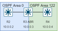
OSPF divides the network into routing areas to simplify administration and optimize traffic and resource utilization. Areas are identified by 32-bit numbers, expressed either simply in decimal, or often in the same octet-based dot-decimal notation used for IPv4 addresses. By convention, area 0 (zero), or 0.0.0.0, represents the core or backbone area of an OSPF network. While the identifications of other areas may be chosen at will, administrators often select the IP address of a main router in an area as the area identifier. Each additional area must have a connection to the OSPF backbone area. Such connections are maintained by an interconnecting router, known as an area border router (ABR). An ABR maintains separate link-state databases for each area it serves and maintains summarized routes for all areas in the network.
OSPF runs over IPv4 and IPv6, but does not use a transport protocol such as UDP or TCP. It encapsulates its data directly in IP packets with protocol number 89. This is in contrast to other routing protocols, such as the Routing Information Protocol (RIP) and the Border Gateway Protocol (BGP). OSPF implements its own transport error detection and correction functions. OSPF also uses multicast addressing for distributing route information within a broadcast domain. It reserves the multicast addresses 224.0.0.5 (IPv4) and ff02::5 (IPv6) for all SPF/link state routers (AllSPFRouters) and 224.0.0.6 (IPv4) and ff02::6 (IPv6) for all Designated Routers (AllDRouters).: 185 : 57 For non-broadcast networks, special provisions for configuration facilitate neighbor discovery. OSPF multicast IP packets never traverse IP routers, they never travel more than one hop. The protocol may therefore be considered a link layer protocol, but is often also attributed to the application layer in the TCP/IP model. It has a virtual link feature that can be used to create an adjacency tunnel across multiple hops. OSPF over IPv4 can operate securely between routers, optionally using a variety of authentication methods to allow only trusted routers to participate in routing. OSPFv3 (IPv6) relies on standard IPv6 protocol security (IPsec), and has no internal authentication methods.
For routing IP multicast traffic, OSPF supports the Multicast Open Shortest Path First (MOSPF) protocol. Cisco does not include MOSPF in their OSPF implementations. Protocol Independent Multicast (PIM) in conjunction with OSPF or other IGPs, is widely deployed.
OSPF version 3 introduces modifications to the IPv4 implementation of the protocol. Except for virtual links, all neighbor exchanges use IPv6 link-local addressing exclusively. The IPv6 protocol runs per link, rather than based on the subnet. All IP prefix information has been removed from the link-state advertisements and from the hello discovery packet making OSPFv3 essentially protocol-independent. Despite the expanded IP addressing to 128 bits in IPv6, area and router Identifications are still based on 32-bit numbers.
Router relationships edit
| Network type | Point to point (P2P) | Broadcast (default) | Non-broadcast multi-access (NBMA) | Point to multipoint | Point to multipoint non broadcast (P2MP-NB) | Passive |
|---|---|---|---|---|---|---|
| Max routers per network | 2 | Unlimited | Unlimited | Unlimited | Unlimited | na |
| Full mesh assumed | Yes | Yes | Yes | No | No | na |
| Hello (default Cisco) | 10 | 10 | 30 | 30 | 30 | na |
| Dead timers (default Cisco) | 40 | 40 | 120 | 120 | 120 | na |
| Wait timer: | 0 | equal to dead timer | equal to dead timer | 0 | 0 | na |
| Automatic neighbour discovery | Yes | Yes | No | Yes | No | na |
| Discovery and hellos are sent to | 224.0.0.5 | 224.0.0.5 | Neighbour IP | 224.0.0.5 | Neighbour IP | na |
| Neighbour communication is sent to | 224.0.0.5 | Unicast | Unicast | Unicast | Unicast | na |
| LSAs are sent to: | 224.0.0.5 | DR/BDR: 224.0.0.6 All: 224.0.0.5 |
DR/BDR: 224.0.0.6 All: 224.0.0.5 |
Unicast | Unicast | na |
| Next-hop IP: | Peer | Original router | Original router | Hub | Hub | na |
| Imported in to OSPF as: | Stub and P2P | Transit | Transit | Stub and P2P | Stub and P2P | Stub |
OSPF supports complex networks with multiple routers, including backup routers, to balance traffic load on multiple links to other subnets. Neighboring routers in the same broadcast domain or at each end of a point-to-point link communicate with each other via the OSPF protocol. Routers form adjacencies when they have detected each other. This detection is initiated when a router identifies itself in a hello protocol packet. Upon acknowledgment, this establishes a two-way state and the most basic relationship. The routers in an Ethernet or Frame Relay network select a designated router (DR) and a backup designated router (BDR) which act as a hub to reduce traffic between routers. OSPF uses both unicast and multicast transmission modes to send "hello" packets and link-state updates.
As a link-state routing protocol, OSPF establishes and maintains neighbor relationships for exchanging routing updates with other routers. The neighbor relationship table is called an adjacency database. Two OSPF routers are neighbors if they are members of the same subnet and share the same area ID, subnet mask, timers and authentication. In essence, OSPF neighborship is a relationship between two routers that allow them to see and understand each other but nothing more. OSPF neighbors do not exchange any routing information – the only packets they exchange are hello packets. OSPF adjacencies are formed between selected neighbors and allow them to exchange routing information. Two routers must first be neighbors and only then, can they become adjacent. Two routers become adjacent if at least one of them is designated router or backup designated router (on multiaccess-type networks), or they are interconnected by a point-to-point or point-to-multipoint network type. For forming a neighbor relationship between, the interfaces used to form the relationship must be in the same OSPF area. While an interface may be configured to belong to multiple areas, this is generally not practiced. When configured in a second area, an interface must be configured as a secondary interface.
Operation modes edit
The OSPF can have different operation modes on the following setups on an interface or network:
- Point-to-point. Each router advertises itself by periodically multicasting hello packets. No designated router is elected. The interface can be IP unnumbered (without a unique IP address assigned to it).
- Broadcast (default), each router advertises itself by periodically multicasting hello packets.
- Non-broadcast multi-access, with the use of designated routers. May need static configuration. Packets are sent as unicast.
- Point-to-multipoint, where OSPF treats neighbours as a collection of point-to-point links. No designated router is elected. Separate hello packets are sent to each neighbor.
- Point to Multipoint Non Broadcast (P2MP-NB), No designated router is elected. Separate hello packets are sent to each neighbor, Packets are sent as unicast.
- Passive, Only advertised to other neighbours. No adjacency is advertised on network.
Indirect connections edit
Virtual link over Virtual links, tunneling and sham links, are a form of connections that goes over the routing engine, and is not a direct connection to the remote host.
- Virtual links: The packets are sent as unicast. Can only be configured on a non-backbone area (but not stub-area). Endpoints need to be ABR, the virtual links behave as unnumbered point-to-point connections. The cost of an intra-area path between the two routers is added to the link.
- Virtual link over tunneling (like GRE and WireGuard): Since OSPF does not support virtual links for areas other than the backbone, a workaround is to use of tunneling. If the same IP or router ID is used, the link creates two equal-cost routes to the destination.
- Sham link: An intra-area link that connects two sites via the MPLS VPN backbone that is preferred to an internal intra-area "OSPF backdoor link" between the same two sites. A sham link is only needed if the MPLS VPN backbone is preferred over the OSPF backdoor link.
Adjacency state machine edit
Each OSPF router within a network communicates with other neighboring routers on each connecting interface to establish the states of all adjacencies. Every such communication sequence is a separate conversation identified by the pair of router IDs of the communicating neighbors. RFC 2328 specifies the protocol for initiating these conversations (Hello Protocol) and for establishing full adjacencies (database description packets, link-state request packets). During its course, each router conversation transitions through a maximum of eight conditions defined by a state machine:
Neighbor state changes edit

Database exchange edit

- Exchange start (exstart): The exstart state is the first step of adjacency of two routers.
- Exchange: In the exchange state, a router is sending its link-state database information to the adjacent neighbor. At this state, a router can exchange all OSPF routing protocol packets.
- Loading: In the loading state, a router requests the most recent link-state advertisements (LSAs) from its neighbor discovered in the previous state.
- Full: The full state concludes the conversation when the routers are fully adjacent, and the state appears in all router- and network-LSAs. The link-state databases of the neighbors are fully synchronized.
Broadcast networks edit
In broadcast multiple-access networks, neighbor adjacency is formed dynamically using multicast hello packets to 224.0.0.5.
IP 192.0.2.1 > 224.0.0.5: OSPFv2, hello
IP 192.0.2.2 > 224.0.0.5: OSPFv2, hello
IP 192.0.2.1 > 192.0.2.2: OSPFv2, database description
IP 192.0.2.2 > 192.0.2.1: OSPFv2, database description
Passive network edit
A network where OSPF adverts the network, but the OSPF will not start neighbour adjacency.
Non-broadcast networks edit
In a non-broadcast multiple-access (NBMA) network, a neighbor adjacency is formed by sending unicast packets to another router. A non-broadcast network can have more than two routers, but broadcast is not supported.
IP 192.0.2.1 > 192.0.2.2: OSPFv2, hello
IP 192.0.2.2 > 192.0.2.1: OSPFv2, hello
IP 192.0.2.1 > 192.0.2.2: OSPFv2, database description
IP 192.0.2.2 > 192.0.2.1: OSPFv2, database description
Examples of non-broadcast networks:
- X.25 public data network
- Wireguard
- Serial interface
- Requires all routers to be able to communicate directly, on the same network.
- Designated Router is elected for the network.
- LSA is generated for the network.
OSPF areas edit
A network is divided into OSPF areas that are logical groupings of hosts and networks. An area includes its connecting router having an interface for each connected network link. Each router maintains a separate link-state database for the area whose information may be summarized towards the rest of the network by the connecting router. Thus, the topology of an area is unknown outside the area. This reduces the routing traffic between parts of an autonomous system.
OSPF can handle thousands of routers with more a concern of reaching capacity of the forwarding information base (FIB) table when the network contains lots of routes and lower-end devices. Modern low-end routers have a full gigabyte of RAM, which allows them to handle many routers in an area 0. Many resources refer to OSPF guides from over 20 years ago where it was impressive to have 64 MB of RAM.
Areas are uniquely identified with 32-bit numbers. The area identifiers are commonly written in the dot-decimal notation, familiar from IPv4 addressing. However, they are not IP addresses and may duplicate, without conflict, any IPv4 address. The area identifiers for IPv6 implementations (OSPFv3) also use 32-bit identifiers written in the same notation. When dotted formatting is omitted, most implementations expand area 1 to the area identifier 0.0.0.1, but some have been known to expand it as 1.0.0.0.
Several vendors (Cisco, Allied Telesis, Juniper, Alcatel-Lucent, Huawei, Quagga), implement totally stubby and NSSA totally stubby area for stub and not-so-stubby areas. Although not covered by RFC standards, they are considered by many to be standard features in OSPF implementations.
OSPF defines several area types:
- Backbone
- Non-backbone/regular
- Stub
- Totally stubby
- Not-so-stubby
- Totally not-so-stubby
- Transit
Backbone area edit

The backbone area (also known as area 0 or area 0.0.0.0) forms the core of an OSPF network. All other areas are connected to it, either directly or through other routers. OSPF requires this to prevent routing loops. Inter-area routing happens via routers connected to the backbone area and to their own associated areas. It is the logical and physical structure for the 'OSPF domain' and is attached to all nonzero areas in the OSPF domain. In OSPF the term autonomous system boundary router (ASBR) is historic, in the sense that many OSPF domains can coexist in the same Internet-visible autonomous system, RFC 1996.
All OSPF areas must connect to the backbone area. This connection, however, can be through a virtual link. For example, assume area 0.0.0.1 has a physical connection to area 0.0.0.0. Further assume that area 0.0.0.2 has no direct connection to the backbone, but this area does have a connection to area 0.0.0.1. Area 0.0.0.2 can use a virtual link through the transit area 0.0.0.1 to reach the backbone. To be a transit area, an area has to have the transit attribute, so it cannot be stubby in any way.
Regular area edit
A regular area is just a non-backbone (nonzero) area without specific feature, generating and receiving summary and external LSAs. The backbone area is a special type of such area.
Stub area edit
- In hello packets the E-flag is not high, indicating "External routing: not capable"
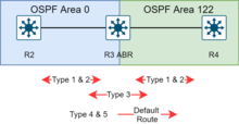
A stub area is an area that does not receive route advertisements external to the AS and routing from within the area is based entirely on a default route. An ABR deletes type 4 and 5 LSAs from internal routers, sends them a default route of 0.0.0.0 and turns itself into a default gateway. This reduces LSDB and routing table size for internal routers.
Modifications to the basic concept of stub area have been implemented by systems vendors, such as the totally stubby area (TSA) and the not-so-stubby area (NSSA), both an extension in Cisco Systems routing equipment.
Totally stubby area edit
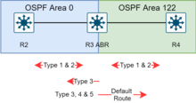
A totally stubby area is similar to a stub area. However, this area does not allow summary routes in addition to not having external routes, that is, inter-area (IA) routes are not summarized into totally stubby areas. The only way for traffic to get routed outside the area is a default route which is the only Type-3 LSA advertised into the area. When there is only one route out of the area, fewer routing decisions have to be made by the route processor, which lowers system resource utilization.
- Occasionally, it is said that a TSA can have only one ABR.[18]
Not-so-stubby area edit

- In hello packets the N-flag is set high, indicating "NSSA: supported"
A not-so-stubby area (NSSA) is a type of stub area that can import autonomous system external routes and send them to other areas, but still cannot receive AS-external routes from other areas.[19]
NSSA is an extension of the stub area feature that allows the injection of external routes in a limited fashion into the stub area. A case study simulates an NSSA getting around the stub-area problem of not being able to import external addresses. It visualizes the following activities: the ASBR imports external addresses with a type 7 LSA, the ABR converts a type 7 LSA to type 5 and floods it to other areas, the ABR acts as an ASBR for other areas. The ASBRs do not take type 5 LSAs and then convert to type 7 LSAs for the area.
Totally not-so-stubby area edit

An addition to the standard functionality of an NSSA, the totally stubby NSSA is an NSSA that takes on the attributes of a TSA, meaning that type 3 and 4 summary routes are not flooded into this type of area. It is also possible to declare an area both totally stubby and not-so-stubby, which means that the area will receive only the default route from area 0.0.0.0, but can also contain an autonomous system boundary router (ASBR) that accepts external routing information and injects it into the local area, and from the local area into area 0.0.0.0.
- Redistribution into an NSSA area creates a special type of LSA known as type 7, which can exist only in an NSSA area. An NSSA ASBR generates this LSA, and an NSSA ABR router translates it into a type 5 LSA, which gets propagated into the OSPF domain.
A newly acquired subsidiary is one example of where it might be suitable for an area to be simultaneously not-so-stubby and totally stubby if the practical place to put an ASBR is on the edge of a totally stubby area. In such a case, the ASBR does send externals into the totally stubby area, and they are available to OSPF speakers within that area. In Cisco's implementation, the external routes can be summarized before injecting them into the totally stubby area. In general, the ASBR should not advertise default into the TSA-NSSA, although this can work with extremely careful design and operation, for the limited special cases in which such an advertisement makes sense.
By declaring the totally stubby area as NSSA, no external routes from the backbone, except the default route, enter the area being discussed. The externals do reach area 0.0.0.0 via the TSA-NSSA, but no routes other than the default route enter the TSA-NSSA. Routers in the TSA-NSSA send all traffic to the ABR, except to routes advertised by the ASBR.
Router types edit
OSPF defines the following overlapping categories of routers:
- Internal router (IR)
- An internal router has all its interfaces belonging to the same area.
- Area border router (ABR)
- An area border router is a router that connects one or more areas to the main backbone network. It is considered a member of all areas it is connected to. An ABR keeps multiple instances of the link-state database in memory, one for each area to which that router is connected.
- Backbone router (BR)
- A backbone router has an interface to the backbone area. Backbone routers may also be area routers, but do not have to be.
- Autonomous system boundary router (ASBR)
- An autonomous system boundary router is a router that is connected by using more than one routing protocol and that exchanges routing information with routers autonomous systems. ASBRs typically also run an exterior routing protocol (e.g., BGP), or use static routes, or both. An ASBR is used to distribute routes received from other, external ASs throughout its own autonomous system. An ASBR creates External LSAs for external addresses and floods them to all areas via ABR. Routers in other areas use ABRs as next hops to access external addresses. Then ABRs forward packets to the ASBR that announces the external addresses.
The router type is an attribute of an OSPF process. A given physical router may have one or more OSPF processes. For example, a router that is connected to more than one area, and which receives routes from a BGP process connected to another AS, is both an area border router and an autonomous system boundary router.
Each router has an identifier, customarily written in the dotted-decimal format (e.g., 1.2.3.4) of an IP address. This identifier must be established in every OSPF instance. If not explicitly configured, the highest logical IP address will be duplicated as the router identifier. However, since the router identifier is not an IP address, it does not have to be a part of any routable subnet in the network, and often isn't to avoid confusion.
Non-point-to-point network edit

On networks (same subnet) with networks type of:
- Broadcast
- Non-Broadcast Multi-Access (NBMA)
A system of designated router (DR) and backup designated router (BDR), is used to reducing network traffic by providing a source for routing updates. This is done using multicast addresses:
- 224.0.0.5, all routers in the topology will listen on that multicast address.
- 224.0.0.6, DR and BDR will listen on that multicast address.
The DR and BDR maintains a complete topology table of the network and sends the updates to the other routers via multicast. All routers in a multi-access network segment will form a leader/follower relationship with the DR and BDR. They will form adjacencies with the DR and BDR only. Every time a router sends an update, it sends it to the DR and BDR on the multicast address 224.0.0.6. The DR will then send the update out to all other routers in the area, to the multicast address 224.0.0.5. This way all the routers do not have to constantly update each other, and can rather get all their updates from a single source. The use of multicasting further reduces the network load. DRs and BDRs are always setup/elected on OSPF broadcast networks. DR's can also be elected on NBMA (Non-Broadcast Multi-Access) networks such as Frame Relay or ATM. DRs or BDRs are not elected on point-to-point links (such as a point-to-point WAN connection) because the two routers on either side of the link must become fully adjacent and the bandwidth between them cannot be further optimized. DR and non-DR routers evolve from 2-way to full adjacency relationships by exchanging DD, Request, and Update.
Designated router edit
A designated router (DR) is the router interface elected among all routers on a particular multiaccess network segment, generally assumed to be broadcast multiaccess. Special techniques, often vendor-dependent, may be needed to support the DR function on non-broadcast multiaccess (NBMA) media. It is usually wise to configure the individual virtual circuits of an NBMA subnet as individual point-to-point lines; the techniques used are implementation-dependent.
Backup designated router edit
A backup designated router (BDR) is a router that becomes the designated router if the current designated router has a problem or fails. The BDR is the OSPF router with the second-highest priority at the time of the last election.
A given router can have some interfaces that are designated (DR) and others that are backup designated (BDR), and others that are non-designated. If no router is a DR or a BDR on a given subnet, the BDR is first elected, and then a second election is held for the DR.[1]: 75
DR Other edit
A router that has not been selected to be designated router (DR) or backup designated router (BDR). The router forms an adjacency to both the designated router (DR) and the backup designated router (BDR).
For other non (B)DR, the adjacency stops at 2-ways State.
Designated router election edit
The DR is elected based on the following default criteria:
- If the priority setting on an OSPF router is set to 0, that means it can NEVER become a DR or BDR.
- If no DR exists on the network, routes will wait until Wait Timer runs out.
- When a DR fails and the BDR takes over, there is another election to see who becomes the replacement BDR.
- The router sending the Hello packets with the highest priority wins the election.
- If two or more routers tie with the highest priority setting, the router sending the Hello with the highest RID (Router ID) wins. NOTE: a RID is the highest logical (loopback) IP address configured on a router, if no logical/loopback IP address is set then the router uses the highest IP address configured on its active interfaces (e.g. 192.168.0.1 would be higher than 10.1.1.2).
- Usually the router with the second-highest priority number becomes the BDR.
- The priority values range between 0 – 255,[20] with a higher value increasing its chances of becoming DR or BDR.
- If a higher priority OSPF router comes online after the election has taken place, it will not become DR or BDR until (at least) the DR and BDR fail.
- If the current DR 'goes down' the current BDR becomes the new DR and a new election takes place to find another BDR. If the new DR then 'goes down' and the original DR is now available, still previously chosen BDR will become DR.
Routing update flow edit
When DR has Routing update edit
- DR sends LSU to 224.0.0.5
- BDR sends LSUAck to 224.0.0.5
- DR Other sends LSUAck to 224.0.0.6
When BDR has Routing update edit
- BDR sends LSU to 224.0.0.5
- BDR sends LSUAck to 224.0.0.5
- DR Other sends LSUAck to 224.0.0.6
When DR Other has Routing update edit
- DR Other sends LSU to 224.0.0.6
- BDR sends LSA to 224.0.0.5
- BDR sends LSUAck to 224.0.0.5
- Non-source routers, DR Other sends LSUAck to 224.0.0.6
Protocol messages edit
| 1 | 1 | 2 | 4 | 4 | 2 | 2 | 8 |
|---|---|---|---|---|---|---|---|
| Version 2 | Type | Packet length | Router ID | Area ID | Checksum | AuType | Authentication |
| 1 | 1 | 2 | 4 | 4 | 2 | 1 | 1 |
|---|---|---|---|---|---|---|---|
| Version 3 | Type | Packet length | Router ID | Area ID | Checksum | Instance ID | Reserved |
Unlike other routing protocols, OSPF does not carry data via a transport protocol, such as the User Datagram Protocol (UDP) or the Transmission Control Protocol (TCP). Instead, OSPF forms IP datagrams directly, packaging them using protocol number 89 for the IP Protocol field. OSPF defines five different message types, for various types of communication. Multiple packets can be sent per frame.
OSPF uses 5 packet types:
- Hello
- Database description
- Link state request
- Link state update
- Link state acknowledgement
Hello Packet edit
| 24 | 4 | 2 | 1 | 1 | 4 | 4 | 4 | 4 |
|---|---|---|---|---|---|---|---|---|
| Header | ||||||||
| Network Mask | Hello Interval | Options | Router Priority | Router Dead Interval | Designated Router ID | Backup Designated Router ID | Neighbor ID |
| 16 | 4 | 1 | 3 | 2 | 2 | 4 | 4 | 4 |
|---|---|---|---|---|---|---|---|---|
| Header | ||||||||
| Interface ID | Router Priority | Options | Hello Interval | Router Dead Interval | Designated Router ID | Backup Designated Router ID | Neighbor ID |
OSPF's Hello messages are used as a form of greeting, to allow a router to discover other adjacent routers on its local links and networks. The messages establish relationships between neighboring devices (called adjacencies) and communicate key parameters about how OSPF is to be used in the autonomous system or area. During normal operation, routers send hello messages to their neighbors at regular intervals (the hello interval); if a router stops receiving hello messages from a neighbor, after a set period (the dead interval) the router will assume the neighbor has gone down.
Database description (DBD) edit
| 16 or 24 | 2 | 1 | 1 | 1 | 4 | Variable |
|---|---|---|---|---|---|---|
| Header | ||||||
| Interface MTU | Hello Interval | Options | Flags | DD sequence number | LSA Headers |
Database description messages contain descriptions of the topology of the autonomous system or area. They convey the contents of the link-state database (LSDB) for the area from one router to another. Communicating a large LSDB may require several messages to be sent by having the sending device designated as a leader device and sending messages in sequence, with the follower (recipient of the LSDB information) responding with acknowledgments.
Link state packets edit
| 24 | 4 | 4 | 4 |
|---|---|---|---|
| Header | |||
| LS Type | Link State ID | Advertising Router |
| 16 | 2 | 2 | 4 | 4 |
|---|---|---|---|---|
| Header | ||||
| Reserved | LS Type | Link State ID | Advertising Router |
- Link state request (LSR)
- Link state request messages are used by one router to request updated information about a portion of the LSDB from another router. The message specifies the link(s) for which the requesting device wants more current information.
| 24 or 16 | 4 | Variable |
|---|---|---|
| Header | ||
| # LSAs | List of LSAs |
- Link state update (LSU)
- Link-state update messages contain updated information about the state of certain links on the LSDB. They are sent in response to a link state request message, and also broadcast or multicast by routers on a regular basis. Their contents are used to update the information in the LSDBs of routers that receive them.
| 24 or 16 | Variable |
|---|---|
| Header | |
| List of LSAs |
- Link state acknowledgment (LSAck)
- Link-state acknowledgment messages provide reliability to the link-state exchange process, by explicitly acknowledging receipt of a Link State Update message.
| LS type | LS name | Generated by | Description |
|---|---|---|---|
| 1 | Router-LSAs | Each internal router within an area | 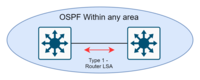 The link-state ID of the type 1 LSA is the originating router ID. Router-LSAs, describe the following types of interfaces:
|
| 2 | Network-LSAs | The DR |  |
| 3 | Summary-LSAs | The ABR |  To inform other areas about inter-area routers. These routes can also be summarised. |
| 4 | ASBR-summary | The ABR | Type 4 describe routes to AS boundary routers beyond its area.
The area border router (ABR) generates this LSA to inform other routers in the OSPF domain, that the matching router is an autonomous system boundary router (ASBR), so that the external LSAs (Type 5 / Type 7) it sent may be properly resolved outside its own area. |
| 5 | AS-external-LSAs | The ASBR |  LSAs contain information imported into OSPF from other routing processes. Together with Type 4 they describe the way to an external route. |
| 7 | NSSA external link-state advertisements | The ASBR, within a not-so-stubby area | Type 7-LSAs are identical to type-5 LSAs. Type-7 LSAs are only flooded within the NSSA. At the area border router, selected type-7 LSAs are translated into type 5-LSAs and flooded into the backbone. |
| 8 | Link-LSA (v3) | Each internal router within a link | Provide it local router's link-local address to all other routers on the local network. |
| 9 | Intra-Area-Prefix-LSAs (v3) | Each internal router within an area | Replaces some of the functionality of Router-LSAs; stub network segment, or an attached transit network segment. |
OSPF v2 area types and accepted LSAs edit
Not all area types use all LSA. Below is a matrix of accepted LSAs.
| Within a single area | Inter area | |||||
|---|---|---|---|---|---|---|
| Area type | LSA 1 - router | LSA 2 - network | LSA 7 - NSSA external | LSA 3 - network summary | LSA 4 - ASBR Summary | LSA 5 - AS external |
| Backbone | Yes | Yes | No, converted into a Type 5 by the ABR | Yes | Yes | Yes |
| Non-backbone | Yes | Yes | No, converted into a Type 5 by the ABR | Yes | Yes | Yes |
| Stub | Yes | Yes | No, Default route | Yes | No, Default route | No, Default route |
| Totally stubby | Yes | Yes | No, Default route | No, Default route | No, Default route | No, Default route |
| Not-so-stubby | Yes | Yes | Yes | Yes | No, Default route | No, Default route |
| Totally not-so-stubby | Yes | Yes | Yes | No, Default route | No, Default route | No, Default route |
Routing metrics edit
OSPF uses path cost as its basic routing metric, which was defined by the standard not to equate to any standard value such as speed, so the network designer could pick a metric important to the design. In practice, it is determined by comparing the speed of the interface to a reference-bandwidth for the OSPF process. The cost is determined by dividing the reference bandwidth by the interface speed (although the cost for any interface can be manually overridden). If a reference bandwidth is set to '10000', then a 10 Gbit/s link will have a cost of 1. Any speeds less than 1 are rounded up to 1.[23] Here is an example table that shows the routing metric or 'cost calculation' on an interface.
- Type-1 LSA has a size of 16-bit field (65,535 in decimal)[24]
- Type-3 LSA has a size of 24-bit field (16,777,216 in decimal)
| Interface speed | Link cost | Uses | |
|---|---|---|---|
| Default (100 Mbit/s) | 200 Gbit/s | ||
| 800 Gbit/s | 1 | 1 | QSFP-DD112 |
| 200 Gbit/s | 1 | 1 | SFP-DD |
| 40 Gbit/s | 1 | 5 | QSFP+ |
| 25 Gbit/s | 1 | 8 | SFP28 |
| 10 Gbit/s | 1 | 20 | 10 GigE, common in data centers |
| 5 Gbit/s | 1 | 40 | NBase-T, Wi-Fi routers |
| 1 Gbit/s | 1 | 200 | common gigabit port |
| 100 Mbit/s | 1 | 2000 | low-end port |
| 10 Mbit/s | 10 | 20000 | 1990's speed. |
OSPF is a layer 3 protocol. If a layer 2 switch is between the two devices running OSPF, one side may negotiate a speed different from the other side. This can create an asymmetric routing on the link (Router 1 to Router 2 could cost '1' and the return path could cost '10'), which may lead to unintended consequences.
Metrics, however, are only directly comparable when of the same type. Four types of metrics are recognized. In decreasing preference (for example, an intra-area route is always preferred to an external route regardless of metric), these types are:
- Intra-area
- Inter-area
- External Type 1, which includes both the external path cost and the sum of internal path costs to the ASBR that advertises the route,[25]
- External Type 2, the value of which is solely that of the external path cost,
OSPF v3 edit
OSPF version 3 introduces modifications to the IPv4 implementation of the protocol.[2] Despite the expansion of addresses to 128 bits in IPv6, area and router identifications are still 32-bit numbers.
High-level changes edit
- Except for virtual links, all neighbor exchanges use IPv6 link-local addressing exclusively. The IPv6 protocol runs per link, rather than based on the subnet.
- All IP prefix information has been removed from the link-state advertisements and from the hello discovery packet, making OSPFv3 essentially protocol-independent.
- Three separate flooding scopes for LSAs:
- Link-local scope: LSA is flooded only on the local link and no further.
- Area scope: LSA is flooded throughout a single OSPF area.
- AS scope: LSA is flooded throughout the routing domain.
- Use of IPv6 link-local addresses, for neighbor discovery, auto-configuration.
- Authentication has been moved to the IP Authentication Header
Changes introduced in OSPF v3, then backported by vendors to v2 edit
- Explicit support for multiple instances per link[26]
Packet format changes edit
- OSPF version number changed to 3
- From the LSA header, the options field has been removed.
- In hello packets and database description, the options field is changed from 16 to 24 bits.
- In hello packet, the address information has been removed. The interface ID has been added.
- In router-LSAs, two options bits, the R-bit and the V6-bit, have been added.
- R-bit: allows for multi-homed hosts to participate in the routing protocol.
- V6-bit: specializes the R-bit.
- Add instance ID, which allows multiple OSPF protocol instances on the same logical interface.
LSA format changes edit
- The LSA type field is changed to 16 bits.
- Add support for handling unknown LSA types
- Three bits are used for encoding flooding scope.
- With IPv6, addresses in LSAs are expressed as prefix and prefix length.
- In router-LSAs and network-LSAs, the address information is removed.
- Router-LSAs and network-LSAs are made network-protocol independent.
- A new LSA type is added, link-LSA, which provides the router's link-local address to all other routers attached to the logical interface, provides a list of IPv6 prefixes to associate with the link, and can send information that reflect the router's capabilities.
- LSA Type-3 summary-LSAs have been renamed "inter-area-prefix-LSAs".
- LSA Type-4 summary LSAs have been renamed "inter-area-router-LSAs".
- Intra-area-prefix-LSA is added, an LSA that carries all IPv6 prefix information.
OSPF over MPLS VPN edit

| Type | Type field | sub value | name |
|---|---|---|---|
| Two-octet AS | 0x00 | 0x05 | OSPF domain identifier |
| Four-octet AS | 0x02 | 0x05 | OSPF domain identifier |
| IPv4 address | 0x01 | 0x05 | OSPF domain identifier |
| IPv4 address | 0x01 | 0x07 | OSPF route ID |
| Opaque | 0x03 | 0x06 | OSPF route type |
| 4 byte | 1 byte | 1 byte |
|---|---|---|
| Area number | Route type | Options |
A customer can use OSPF over a MPLS VPN, where the service provider uses BGP or RIP as their interior gateway protocol.[8] When using OSPF over MPLS VPN, the VPN backbone becomes part of the OSPF backbone area 0. In all areas, isolated copies of the IGP are run.
Advantages:
- The MPLS VPN is transparent to the customer's OSPF standard routing.
- Customer's equipment only needs to support OSPF.
- Reduce the need for tunnels (Generic Routing Encapsulation, IPsec, wireguard) to use OSPF.
To achieve this, a modified OSPF-BGP redistribution is used. All OSPF routes retain the source LSA type and metric.[28][29] To prevent loops, an optional DN bit[30] is set by the service provider in LSAs from the provider equipment to indicate that a route has already been sent to the customer's equipment.
OSPF extensions edit
Traffic engineering edit
OSPF-TE is an extension to OSPF extending the expressivity to allow for traffic engineering and use on non-IP networks.[31] Using OSPF-TE, more information about the topology can be exchanged using opaque LSA carrying type–length–value elements. These extensions allow OSPF-TE to run completely out of band of the data plane network. This means that it can also be used on non-IP networks, such as optical networks.
OSPF-TE is used in GMPLS networks as a means to describe the topology over which GMPLS paths can be established. GMPLS uses its own path setup and forwarding protocols, once it has the full network map.
In the Resource Reservation Protocol (RSVP), OSPF-TE is used for recording and flooding RSVP signaled bandwidth reservations for label-switched paths within the link-state database.
Optical routing edit
RFC 3717 documents work in optical routing for IP based on extensions to OSPF and IS-IS.[32]
Multicast Open Shortest Path First edit
The Multicast Open Shortest Path First (MOSPF) protocol is an extension to OSPF to support multicast routing. MOSPF allows routers to share information about group memberships.
Notable implementations edit
- Allied Telesis implements OSPFv2 & OSPFv3 in Allied Ware Plus (AW+)
- Arista Networks implements OSPFv2 and OSPFv3
- BIRD implements both OSPFv2 and OSPFv3
- Cisco IOS and NX-OS
- Cisco Meraki
- D-Link implements OSPFv2 on Unified Services Router.
- Dell's FTOS implements OSPFv2 and OSPFv3
- ExtremeXOS
- FRRouting, the successor of Quagga
- GNU Zebra, a GPL routing suite for Unix-like systems
- Juniper Junos
- NetWare implements OSPF in its Multi Protocol Routing module.
- OpenBSD includes OpenOSPFD, an OSPFv2 implementation.
- Quagga, a fork of GNU Zebra for Unix-like systems
- Windows NT 4.0 Server, Windows 2000 Server and Windows Server 2003 implemented OSPFv2 in the Routing and Remote Access Service, although the functionality was removed in Windows Server 2008.
- XORP, a routing suite implementing RFC2328 (OSPFv2) and RFC2740 (OSPFv3) for both IPv4 and IPv6
Applications edit
OSPF is a widely deployed routing protocol that can converge a network in a few seconds and guarantee loop-free paths. It has many features that allow the imposition of policies about the propagation of routes that it may be appropriate to keep local, for load sharing, and for selective route importing. IS-IS, in contrast, can be tuned for lower overhead in a stable network, the sort more common in ISP than enterprise networks. There are some historical accidents that made IS-IS the preferred IGP for ISPs, but ISPs today may well choose to use the features of the now-efficient implementations of OSPF,[33] after first considering the pros and cons of IS-IS in service provider environments.[34]
OSPF can provide better load-sharing on external links than other IGPs.[citation needed] When the default route to an ISP is injected into OSPF from multiple ASBRs as a Type I external route and the same external cost specified, other routers will go to the ASBR with the least path cost from its location. This can be tuned further by adjusting the external cost. If the default route from different ISPs is injected with different external costs, as a Type II external route, the lower-cost default becomes the primary exit and the higher-cost becomes the backup only.
See also edit
- Fabric Shortest Path First
- Mesh networking
- Route analytics
- Routing
- Shortest path problem
Ospf Tutorials:
Latest online Ospf Tutorials with example so this page for both freshers and experienced candidate who want to get job in Ospf company
Latest online Ospf Tutorials for both freshers and experienced
advertisementsView Tutorials on Ospf 
- 6 >Hyderabad
- 7 >Kolkata
- 8 >Kochi
- 9 >Ahmedabad
- 10 >Trivandrum
- 11 >Bhubaneshwar
- 12 >Indore
- 13 >Coimbatore
- 14 >Goa
- .Net Interview Questions And Answers
- All Interview Questions And Answers
- Android Common Tips Q and Ans
- AJAX Interview Questions And Answers
- Codeigniter Interview Questions And Answers
- Aptitude Interview Questions And Answers
- C Interview Questions And Answers
- CSS3 Interview Questions And Answers
- Data Structure Questions With Answers
- Database (DBMS) Questions With Answers
- Drupal Interview Questions And Answers
- Download Career Guide in doc file
- Dojo Interview Questions And Answers
- Design Pattern of all type
- EJB Interview Questions And Answers
- Header Function use in PHP and HTTP
- HR Interview Questions And Answers
- HTML5 Interview Questions And Answers
- Joomla Interview Questions And Answers
- Iphone Interview Questions And Answers
- MYSQL Interview Questions And Answers
- Java Interview Questions And Answers
- JQuery Interview Questions And Answers
- JSON Interview Questions And Answers
- JSP Interview Questions And Answers
- linux Commands and Interview Questions
- Moodle Tutorial for Developers
- Magento Common Tips Q and Ans
- Networking Hardware Questions with Answers
- Operating Systems Interview Questions
- OOPs Interview Questions and Answers
- PHP Interview Questions And Answers
- PHP Interview Questions 1500+
- PHP All Objective Questions Answers
- PHP Jobs for freshers and experienced
- Project Management Interview questions
- Regular Expressions Interview questions
- Spring Interview Questions Answers In Java
- Software Testing Interview Questions Answer
- Servlets Interview Questions And Answers
- Struts Interview Questions And Answers
- Threads Interview Questions And Answers
- US Jobs city Wise
- All Indian Company Name List
- Web Designing Interview Questions Answers
- XML Interview Questions Answers
- XML Interview Questions Answers
- .net Interview Questions And Answers
- Accountant Interview Questions And Answers
- Ado.net Interview Questions And Answers
- Adp Interview Questions And Answers
- Agile Methodology Interview Questions And Answers
- Android Interview Questions And Answers
- Apache Interview Questions And Answers
- Application Packaging Interview Questions And Answers
- Asp Interview Questions And Answers
- Backbone.js Interview Questions And Answers
- C Sharp Interview Questions And Answers
- C++ Interview Questions And Answers
- Cake Interview Questions And Answers
- Cakephp Interview Questions And Answers
- Can Protocol Interview Questions And Answers
- Catia V5 Interview Questions And Answers
- Ccna Interview Questions And Answers
- Checkpoint Firewall Interview Questions And Answers
- Control M Interview Questions And Answers
- Cpp Interview Questions And Answers
- Css Interview Questions And Answers
- DATA GRID Interview Questions And Answers
- Data Warehouse Interview Questions And Answers
- Data Structures Interview Questions And Answers
- Database Interview Questions And Answers
- Db2 Interview Questions And Answers
- Desktop Engineer Interview Questions And Answers
- Desktop Support Interview Questions And Answers
- DOJO Interview Questions And Answers
- Electrical Engineering Interview Questions And Answers
- Embedded Systems Interview Questions And Answers
- Hadoop Interview Questions And Answers
- Hibernate Interview Questions And Answers
- J2ee Interview Questions And Answers
- Javascript Interview Questions And Answers
- Joomla Interview Questions And Answers
- Jsp Interview Questions And Answers
- Less Interview Questions And Answers
- Linq Interview Questions And Answers
- Linux Interview Questions And Answers
- Matlab Interview Questions And Answers
- Mcitp Interview Questions And Answers
- Netbackup Interview Questions And Answers
- Node.js Interview Questions And Answers
- Oracle Interview Questions And Answers
- Perl Interview Questions And Answers
- Plsql Interview Questions And Answers
- Postgresql Interview Questions And Answers
- Python Interview Questions And Answers
- Qa Testing Interview Questions And Answers
- Qtp Interview Questions And Answers
- Sap Interview Questions And Answers
- Sass Interview Questions And Answers
- Selenium Interview Questions And Answers
- SEO Interview Questions And Answers
- Sharepoint Interview Questions And Answers
- Silverlight Interview Questions And Answers
- Sql Dba Interview Questions And Answers
- String Interview Questions And Answers
- Struts2 Interview Questions And Answers
- Stware Testing Interview Questions And Answers
- Swing Interview Questions And Answers
- Technical Support Interview Questions And Answers
- Telecom Billing Interview Questions And Answers
- Tomcat Interview Questions And Answers
- Troubleshooting Interview Questions And Answers
- Uml Interview Questions And Answers
- Us Visa Interview Questions And Answers
- Vb Interview Questions And Answers
- Visa Interview Questions And Answers
- Wcf Interview Questions And Answers
- Web Testing Interview Questions And Answers
- Windows Interview Questions And Answers
- Wordpress Interview Questions And Answers
- Wpf Interview Questions And Answers
- XQuery Interview Questions And Answers
- Yii Interview Questions And Answers
- Zend Framework 2 Interview Questions And Answers
- Zend Framework Interview Questions And Answers